Schematic 555 Timer Circuit Diagram - Ic 555 Timer Pin Daigram With Configuration And It S Applications / The 555 ic timer circuit above shows a very straightforward design where the ic 555 forms the central controlling part of the circuit.
byAdmin-
0
Schematic 555 Timer Circuit Diagram - Ic 555 Timer Pin Daigram With Configuration And It S Applications / The 555 ic timer circuit above shows a very straightforward design where the ic 555 forms the central controlling part of the circuit.. Over 100 of 555 timer circuits and projects including the ic datasheet. 555 timer bistable example circuit. 555 timer helpers schematic the addition of a capacitor to the trigger will not work for short output pulses as there This circuit can be used as rain sensor, water overflow sensor or as a water level sensor. Here, we take a look at some 555 timer circuits based on the ic.
See more ideas about timer, electronics circuit, circuit. The 555 timer starts timing when switched on. The 555 timer ic is an integral part of electronics projects. If a 10uf timing capacitor is used, calculate the value of the resistor required to produce a minimum output time delay of 500ms. The following schematic shows two additions to the basic 555 timer circuit.
555 Timer Ic Block Diagram Working Pin Out Configuration Data Sheet from www.circuitstoday.com The working modes of a 555 timer are astable, bistable, and monostable. Use the diagram below to connect the circuit: In monostable mode, the duration for. Once this switch is pushed, the circuit pulls its output to a. 500ms is the same as saying 0.5s so by rearranging the formula above, we get the calculated value for the resistor, r as: 555 datasheet 555 duty cycle 555 metronome 555 reset function 555 time delay relay inverted 555 timer pulse generator. The 555 timer is a simple integrated circuit that can be used to make many different electronic circuits. In this mode, the circuit of the ic 555 timer produces the continuous pulses with exact frequency primarily based on the value of the two resistors and.
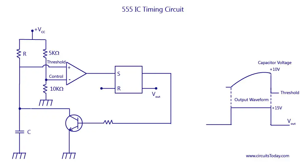
The following schematic shows two additions to the basic 555 timer circuit.
Check out the huge collection of 555 timer based circuits here. Let us discuss in detail about this circuit. The block diagram of a 555 timer is shown in the above figure. As you might already know, a 555 timer can be easily wired as astable, monostable or bistable multivibrator. Simple 555 timer circuits & projects. Although the schematic looks correct, this basic circuit may actually have a few negative aspects. The 555 integrated circuit is the most popular chip ever manufactured. Use the diagram below to connect the circuit: It has been redesigned, improved, and reconfigured in many ways, yet the. Here is a simple and interesting hobby circuit that can be made using the popular 555 timer ic. From our earlier discussions we know that for a 555 in the delay timer mode, the delay could be accurately managed through a single external resistor and one capacitor. Resistive network consists of three equal resistors and acts as a voltage divider. After one minute of time duration, the led will automatically turn on.
555 timer is an industrial standard ic existing from early days of ic. The 555 timer is a simple integrated circuit (ic) that can be used in electronic circuits, projects, and a variety of applications like timer, pulse oscillator, delays, flip flop, etc In this circuit, after you press the button once, the led will light up then turn off. Over 100 of 555 timer circuits and projects including the ic datasheet. Use the diagram below to connect the circuit:
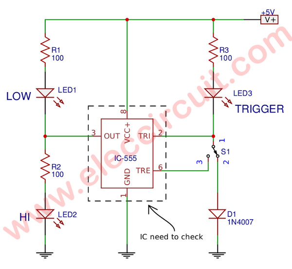
How Does Ne555 Timer Circuit Works Datasheet Pinout Eleccircuit Com from www.eleccircuit.com In this tutorial, we are making a 555 timer circuit. The reset input current draw illustrates the need for a current limiting resistor as shown in some of the preceding circuits. The following example shows the 555 timer in bistable mode. We need to set 555 timer in monostable mode to build timer. The 555 integrated circuit is the most popular chip ever manufactured. 555 timer bistable example circuit. We can use this property of 555 timer to create various timer circuits like 1 minute timer circuit, 5 minute timer circuit, 10 minute timer circuit, 15 minute timer circuit, etc. After one minute of time duration, the led will automatically turn on.
The 555 integrated circuit is the most popular chip ever manufactured.
In this category, we have handpicked some really useful 555 timer circuits which will be interesting to electronics engineering students and hobbyists alike. This project uses a static sensitive part, the cmos 555. Learn one of several 555 timer astable multivibrator configurations; 555 timer was first introduced by signetics corporation in 1971 as se555/ne555. The block diagram of a 555 timer is shown in the above figure. One reduces the trigger sensitivity and the other will double the output pulse duration without increasing the r1 and c1 values. We need to set 555 timer in monostable mode to build timer. Working knowledge of duty cycle; To understand the basic concept of the timer let' s first examine the timer in block form as in figure 1. There are simple circuits for beginners and advanced engineers. This pin should be connected to ground. The 555 timer ic is an integral part of electronics projects. The working modes of a 555 timer are astable, bistable, and monostable.
Let us discuss in detail about this circuit. In this circuit, after you press the button once, the led will light up then turn off. In this mode, the circuit of the ic 555 timer produces the continuous pulses with exact frequency primarily based on the value of the two resistors and. We have a large collection of simple and advanced projects using 555 timer ic. The following example shows the 555 timer in bistable mode.
Simple Dc To Dc Converter Using 555 Time Ic 6v To 35 Volts Boost Converter from i2.wp.com Check out the huge collection of 555 timer based circuits here. 555 timer bistable example circuit. In this category, we have handpicked some really useful 555 timer circuits which will be interesting to electronics engineering students and hobbyists alike. Use the diagram below to connect the circuit: You can for example use it to reverse the direction of a robot when it bumps into a wall. Rain alarm using 555 timer. Figure 1 is the pinout and functional block diagram for the 555 timer ic. 500ms is the same as saying 0.5s so by rearranging the formula above, we get the calculated value for the resistor, r as:
As we know 555 timer ic is one of the commonly used ic among students and hobbyists.
One reduces the trigger sensitivity and the other will double the output pulse duration without increasing the r1 and c1 values. 555 ic timer block diagram 555 ic timer block diagram. See more ideas about timer, electronics circuit, circuit. You can for example use it to reverse the direction of a robot when it bumps into a wall. Daman shah june 5, 2021. Various light actuator and relay driver circuits are also further enclosed. We need to set 555 timer in monostable mode to build timer. This pin should be connected to ground. Although the schematic looks correct, this basic circuit may actually have a few negative aspects. As we know 555 timer ic is one of the commonly used ic among students and hobbyists. Working modes of 555 timer ic. Some devices will not function properly if the current to the threshold input is not restricted. Learn how to handle esd sensitive parts.